
- Home
- About us
-
Products
-
Wood Plastic Composite WPC Machine
-
WPC Machine
 WPC MachineMore
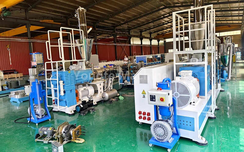
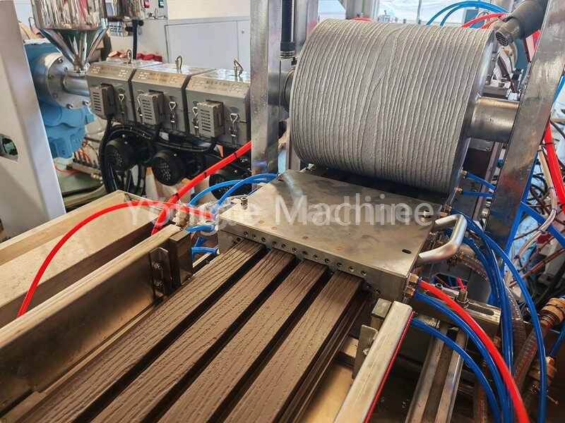
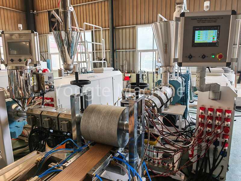
Yongte WPC Machine Turnkey Project offers complete wood plastic composite production solutions with high efficiency, automation, and environmental sustainability. Our machines process recycled PP/PE plastic with 60-70% wood powder content, producing high-quality WPC products for construction, furniture, and landscaping.
-
WPC Door Production Line
 WPC Door Production LineMore
Turnkey WPC door production line - Yongte factory in China, high capacity, high automation, eco-friendly & low maintenance. Global after-sales. lifttime service. free training and experienced formulation. Get custom quote now!
-
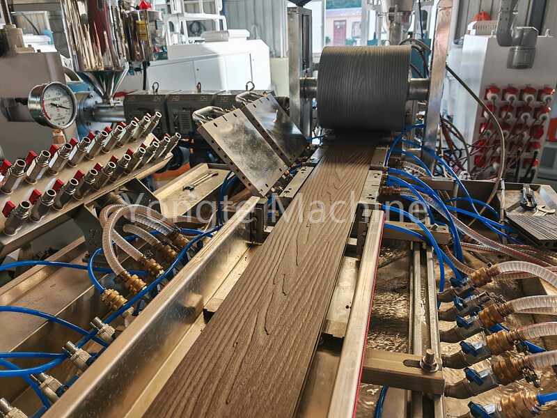
WPC Decking Production Machine
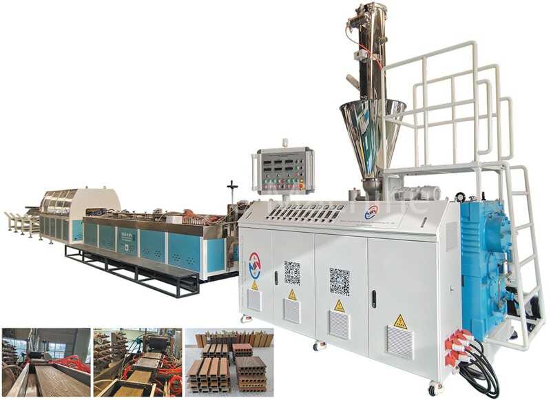 WPC Decking Production MachineMore
CE certified automatic WPC decking production machine - high efficiency, eco-friendly, customizable for outdoor decking boards. 350-450kg/h capacity, turnkey project service, global after-sales & 1-year warranty. Get custom quote now!"
-
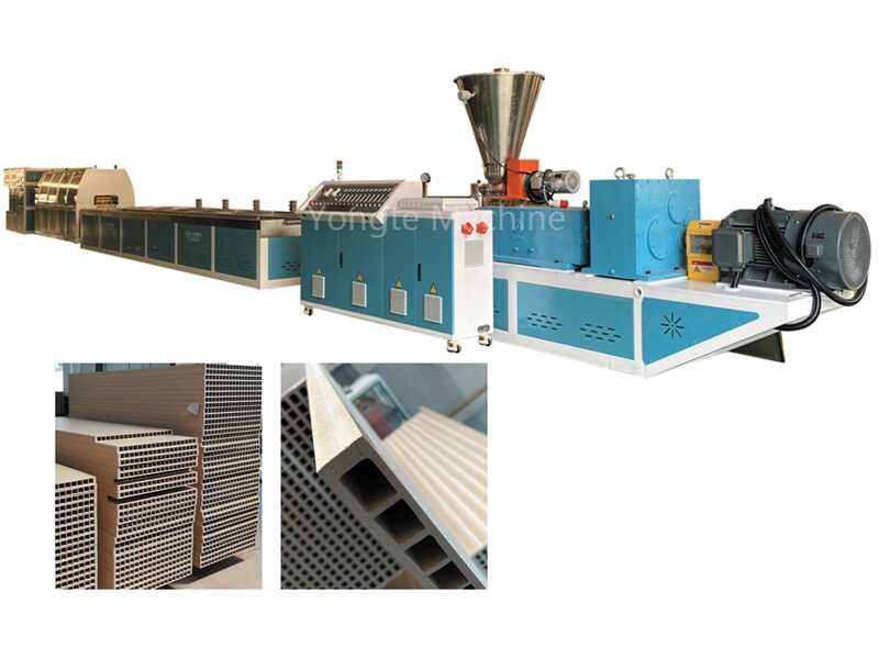
SJSZ65/132 WPC Door Profile Extrusion Line
 SJSZ65/132 WPC Door Profile Extrusion LineMore
Yongte WPC Door Profile Extrusion Line: CE Certified, High automation, Conical twin-screw extruder, 150-250 kg/h capacity. Free warranty & lifetime support
-
WPC Wall Panel Extrusion Line
 WPC Wall Panel Extrusion LineMore
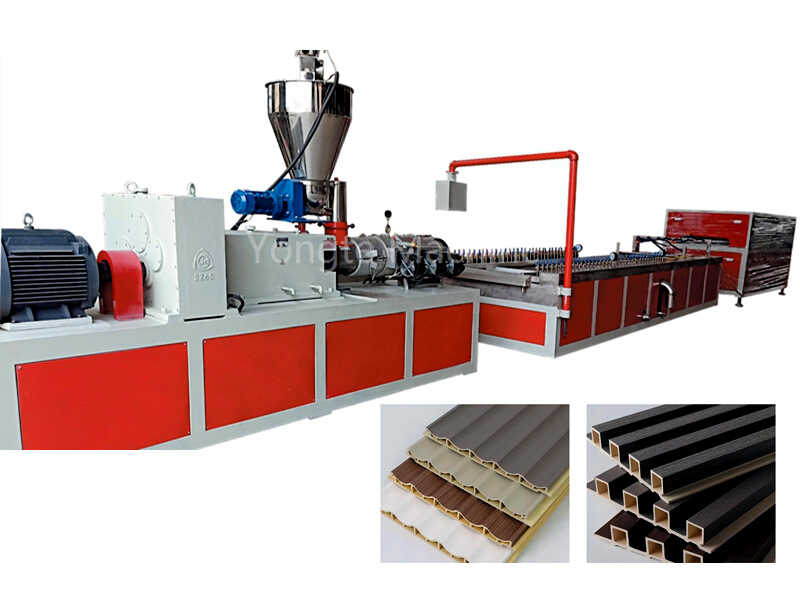
Yongte WPC wall panel extrusion line enables the efficient production of high-quality WPC panels for interior and exterior wall cladding applications. The production line ensures precise control over the extrusion process, resulting in wall panels with consistent dimensions, surface finish, and durability.
-
CE Certified WPC Foam Board Extrusion Line
 CE Certified WPC Foam Board Extrusion LineMore
Yongte WPC Foam Board Extrusion Line produces lightweight, durable PVC/WPC foam boards (1220mm width, 3-40mm thickness). Multi-use for advertising/vehicle decoration, get free warranty & lifetime technical support.
-
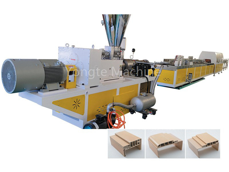
WPC Solid Door Jamb Extrusion Line
 WPC Solid Door Jamb Extrusion LineMore
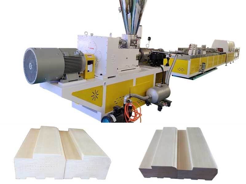
Yongte WPC Solid Door Jamb Extrusion Line has many advantages such as high efficiency, high quality, energy saving and environmental protection, easy operation, flexible adaptability, low maintenance cost, safety and reliability, continuous innovation and professional services. it is an ideal choice
-
Yongte WPC Decking Co-extrusion Line | CE Certified Recycled PP PE Solution
 Yongte WPC Decking Co-extrusion Line | CE Certified Recycled PP PE SolutionMore
Yongte WPC Decking Co-extrusion Line: CE certified, uses recycled PP/PE. Wear-resistant, wood-grain finish, 100-300kg/h. WhatsApp +8613583233866 for custom quote!
-
Wood Plastic Composite Production Line
 Wood Plastic Composite Production LineMore
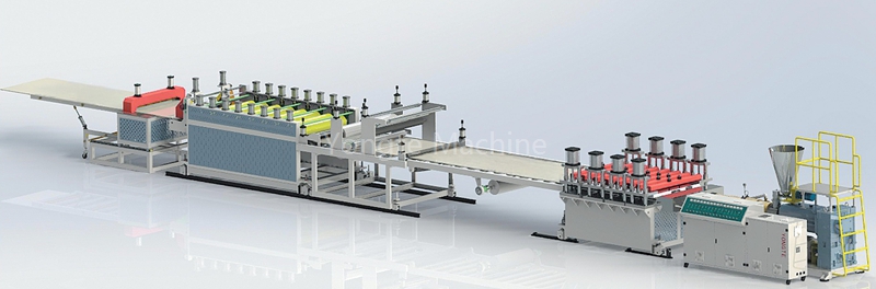
Yongte Wood-Plastic Composite Production Line Turnkey Project delivers end-to-end solutions for highly efficient, fully automated, and environmentally sustainable production of wood-plastic composites. Our machinery processes recycled PP/PE plastics blended with 60-70% wood powder content, producing premium WPC products ideal for construction, furniture, and landscaping applications
-
WPC Wall Cladding Making Machine
WPC Wall Cladding Making MachineMore
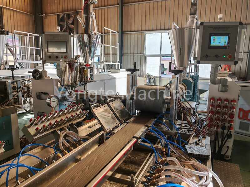
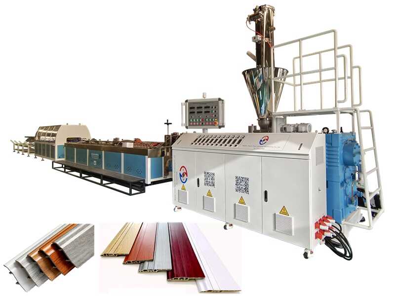
Yongte WPC Wall Cladding Making Machine is used for making WPC wall cladding products from recycled PP/PE plastic and wood powder composited material, it has the advantages of high efficiency, high quality, energy saving, easy operation, low maintenance cost, and continuous innovation, We supply complete equipment and turn-key service for making WPC product from raw material to the finished products.
-
WPC Granulation Machine
 WPC Granulation MachineMore
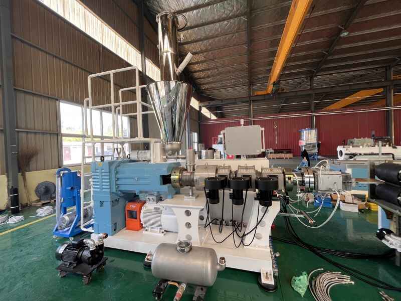
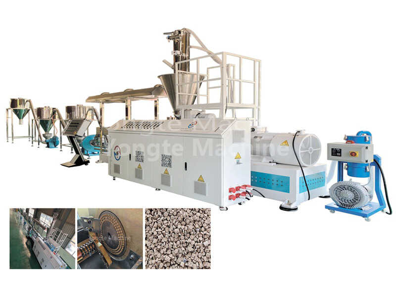
WPC granulation machine is used for making WPC granules from wood andplastic mixture. lt contents the feeding device, parallel double screw extruder,primary crushing device, 4 stages cooling device, fine crusher and material tank.Yongte WPC granulation machine has the advantages of high efficiency,c
-
Recycled PP PE WPC Profile Extrusion Line
 Recycled PP PE WPC Profile Extrusion LineMore
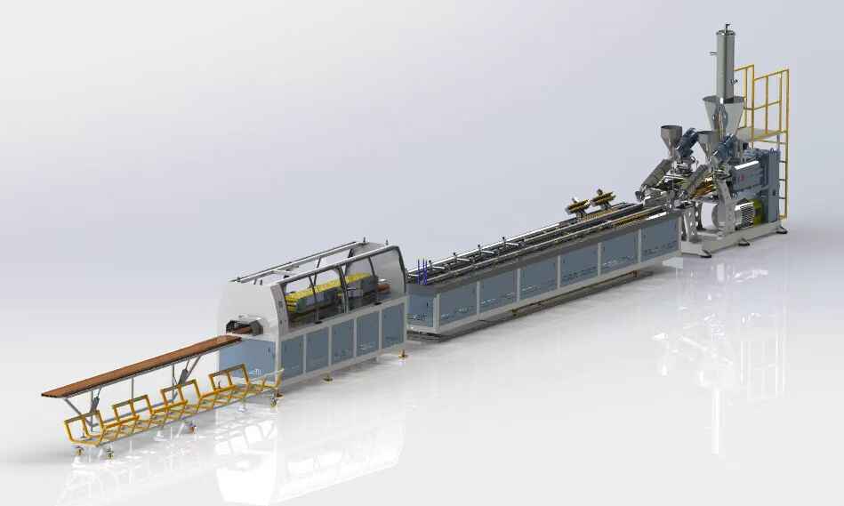
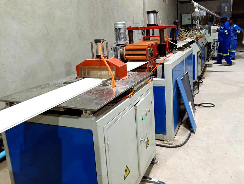
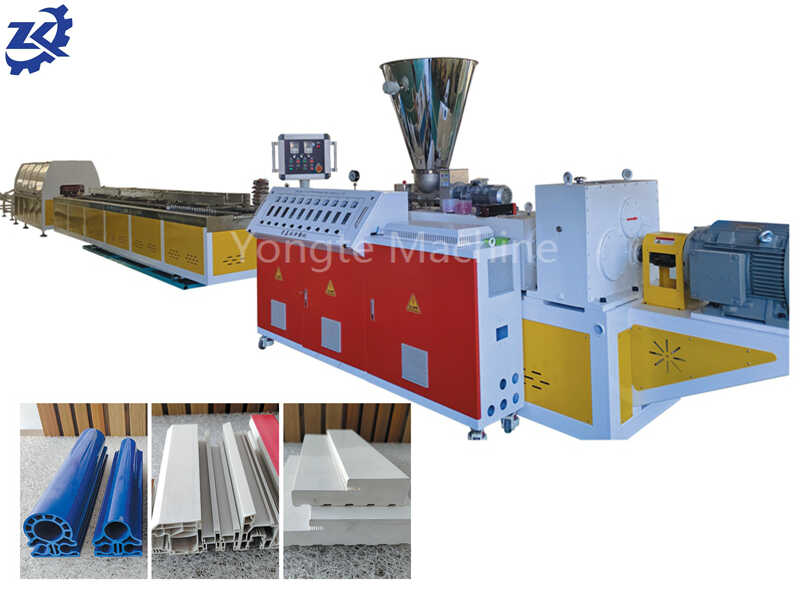
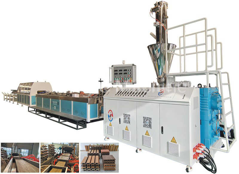
Yongte Recycled PP PE WPC Extrusion Line: CE Certified turnkey solution for eco-friendly profiles. 150-450kg/h capacity, energy-saving & cost-effective—WhatsApp for custom quote!
-
WPC Machine
-
Plastic Pipe Production Line
-
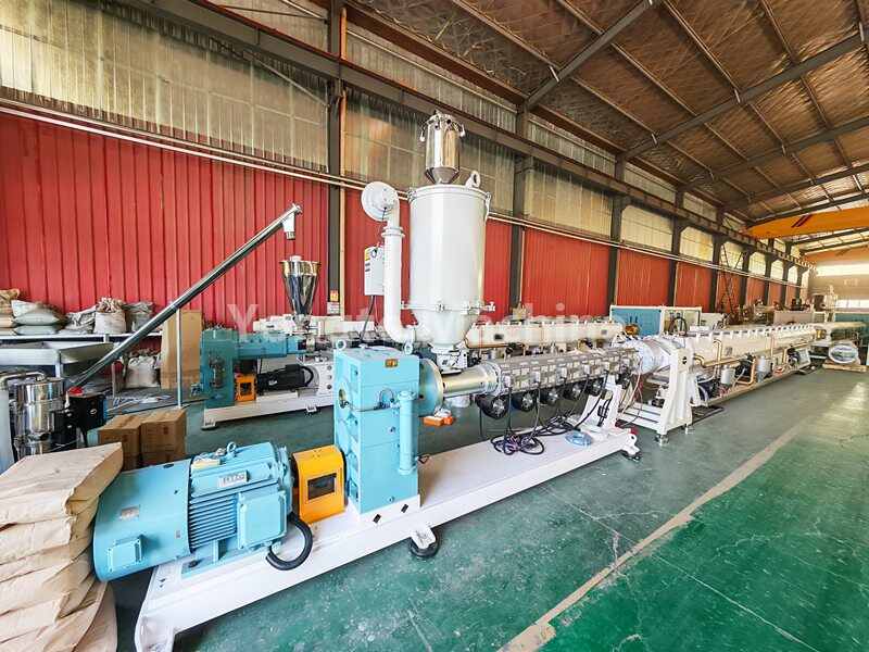
16-63mm PPR Pipe Extrusion Line
 16-63mm PPR Pipe Extrusion LineMore
Yongte High-Performance 16-63mm PPR Pipe Extrusion Line - for mono/three-layer PPR pipes (residential/commercial/industrial hot water supply). Features state-of-the-art extrusion tech, full automation & precision cooling, ensuring uniform thickness, low manual intervention & cost-effective production.
-
PVC Pipe Extruder Machine
 PVC Pipe Extruder MachineMore
Yongte PVC Pipe Extruder Machine adopts high effencieny, high speed, high automatic, easy operation and factory price.
-
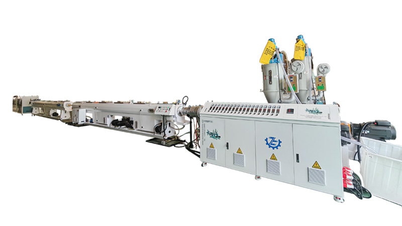
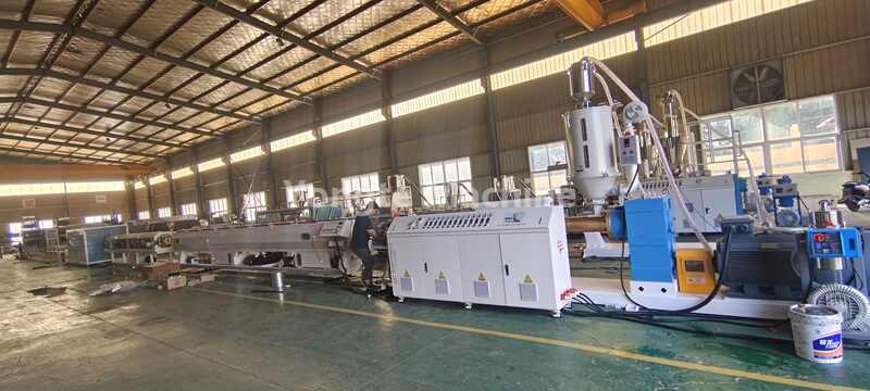
Yongte PE Pipe Production Line (16-630mm) | High Automatic, CE Cerified, High effeciency
 Yongte PE Pipe Production Line (16-630mm) | High Automatic, CE Cerified, High effeciencyMore
Yongte PE Pipe Production Line (16-630mm): CE certified, High-precision, automated, high effeciency, 120-500kg/h. For water/gas/chemicals. Custom solutions + free warranty+lifetime support.
-
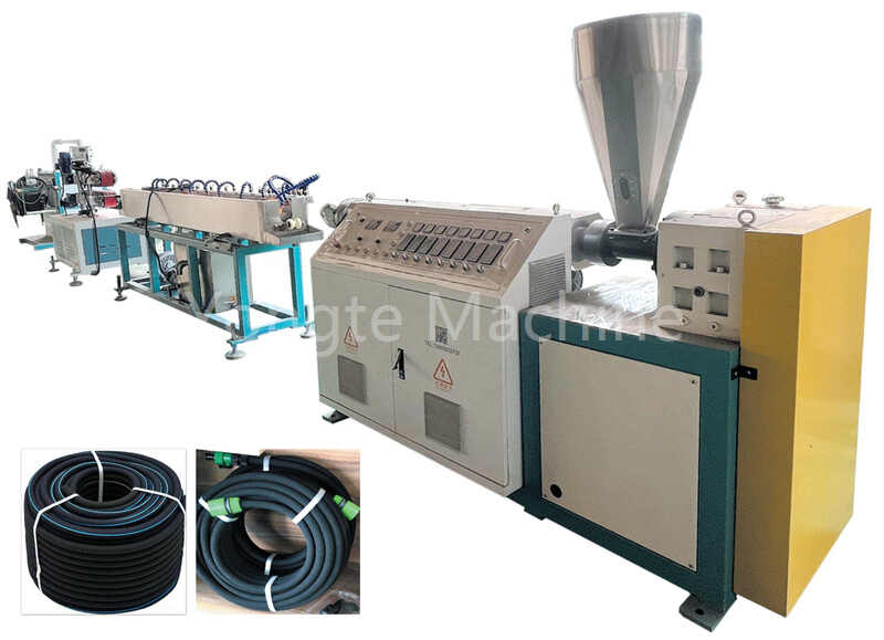
9-32mm Rubber Irrigation Pipe Making Machine
 9-32mm Rubber Irrigation Pipe Making MachineMore
Yongte 9-32mm Rubber Irrigation Pipe Making Machine: Waste tire recycling + nano technology for anti-clogging, eco-friendly pipes. Suitable for agricultural irrigation, sponge cities & sewage treatment—water-saving, durable & cost-effective.
-
20-110mm Three layer PPR Pipe Extrusion Machine
 20-110mm Three layer PPR Pipe Extrusion MachineMore
Yongte 20-110mm Three layer PPR Pipe Extrusion Machine is used for making PPR pipe with ABA three layer, the PPR pipe is widely used for hot water supply. It uses advanced co-extrusion technology, high speed cooling and calibrating system, automatic pull and cutting machine, automatic feeding and discharge system, automatic temperature control system. it has advantages of high production capacity, high speed production, low power consumption, high automatic, easy operation, easy maintainence.
-
75-160mm PPR pipe making machine
 75-160mm PPR pipe making machineMore
Yongte 75-160mm PPR pipe making machine: Professional Manufacturer, CE certified, high speed production, high precision and uniform pipe size, high automatic, 16-160mm pipe size
-
MPP Electric Conduit Pipe Making Machine
 MPP Electric Conduit Pipe Making MachineMore
MPP (Modified Polypropylene) power pipe equipment is the core equipment for producing high-performance power cable protection pipes. Yongte MPP Electric Conduit Pipe Making Machine boasts advantages such as high production efficiency, high automation, energy saving and environmental protection, and easy operation and maintenance.
-
315-630mm PVC Pipe Production Machine
 315-630mm PVC Pipe Production MachineMore
Yongte 315-630mm PVC Pipe Production Machine is a complete set of equipment that processes PVC raw materials into pipes through a continuous extrusion molding process. Its core is the automation of the raw material melting, molding, shaping, and cutting process. The stability of this process directly determines the dimensional accuracy and physical properties of the pipes.
-
50-160mm Water Supply/Drainage PVC Pipe Manufacturing Machine
 50-160mm Water Supply/Drainage PVC Pipe Manufacturing MachineMore
Yongte 50-160mm PVC Pipe Manufacturing Machine: CE certified, Energy-saving (30%+ vs traditional) servo-driven equipment for water supply, irrigation & power protection. High-precision, high automatic, continuous production with SJSZ65/132 extruder.
-
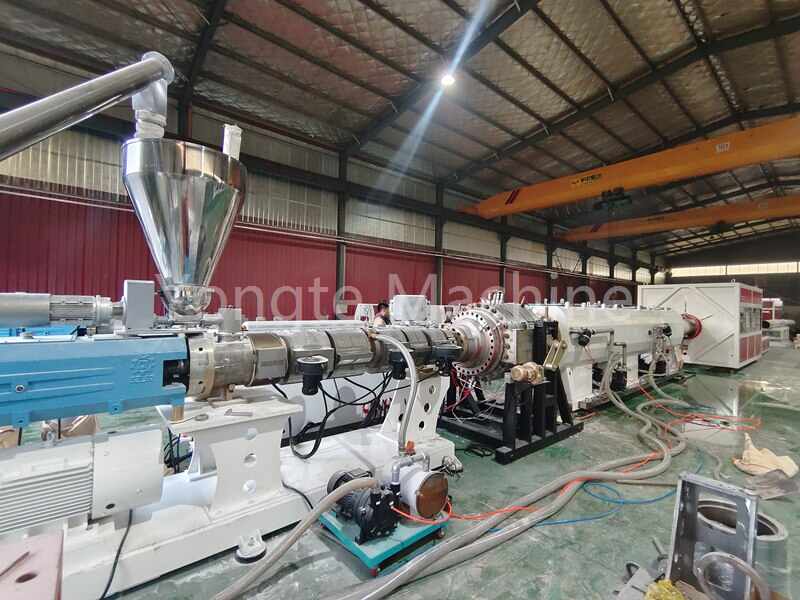
280-630mm HDPE Pipe Production Line
 280-630mm HDPE Pipe Production LineMore
Yongte 280-630mm HDPE Pipe Production Line adopts the world's leading extrusion technology to ensure the dimensional accuracy and quality stability of the pipe. The high-precision mold design makes the inner and outer walls of the PE pipe smooth and flat without any defects. The advanced control system can monitor and adjust various parameters in the production process in real time to ensure that each PE pipe meets strict quality standards.
-
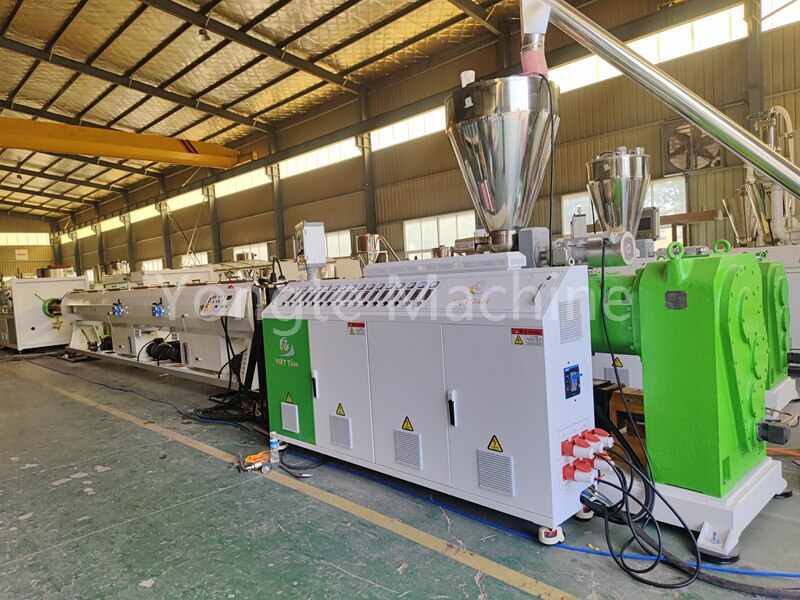
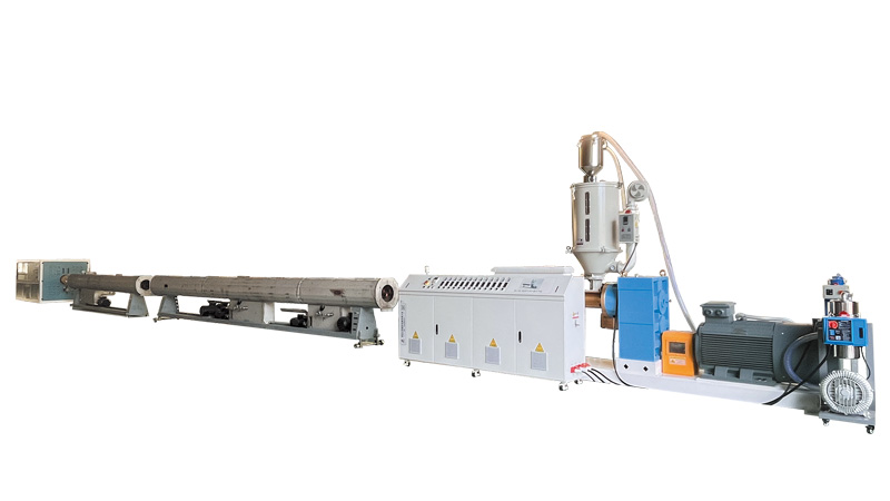
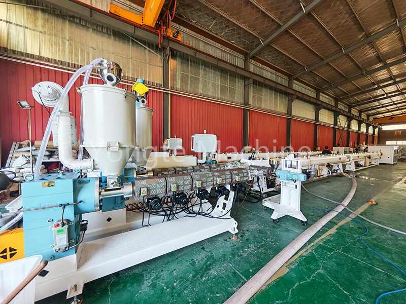
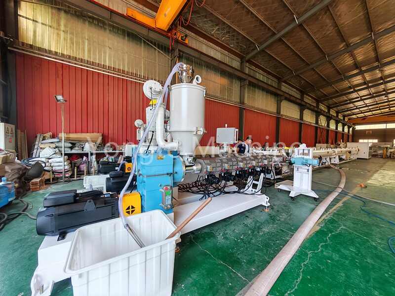
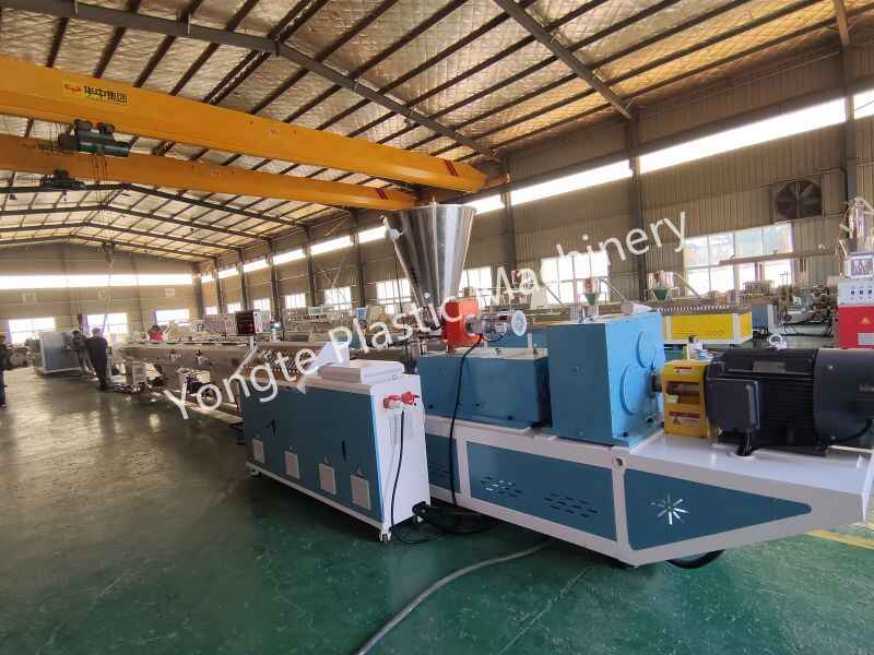
75-250mm PE Pipe Production Line
 75-250mm PE Pipe Production LineMore
Yongte75-250mm PE pipe production line is used for making PE water supply or gas supply pipe. The equipment uses advanced extrusion technology to ensure accurate size and stable quality of the pipe. Its high-speed operation capability greatly improves production efficiency. Easy to operate, in
-
110-315mm PVC Pipe Extrusion Line
 110-315mm PVC Pipe Extrusion LineMore
Yongte 110-315mm PVC Pipe Extrusion Line is a complete set of equipment that processes PVC raw materials into pipes through a continuous extrusion molding process. Its core is the automation of the raw material melting, molding, shaping, and cutting process. The stability of this process directly determines the dimensional accuracy and physical properties of the pipes.
-
16-63mm PPR Pipe Extrusion Line
-
Plastic Profile Production Line
-
ABS Profile Extrusion Machine
 ABS Profile Extrusion MachineMore
Yongte ABS profile extrusion machine is a specialized equipment used in the manufacturing process of extruding ABS (Acrylonitrile Butadiene Styrene) plastic material into various profiles or shapes. ABS profiles are commonly used in a wide range of applications, including automotive trims, electronics housings, construction components, and consumer products.
-
PVC Rain Gutter Manufacturing Machine
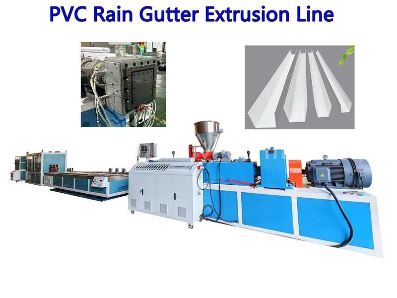 PVC Rain Gutter Manufacturing MachineMore
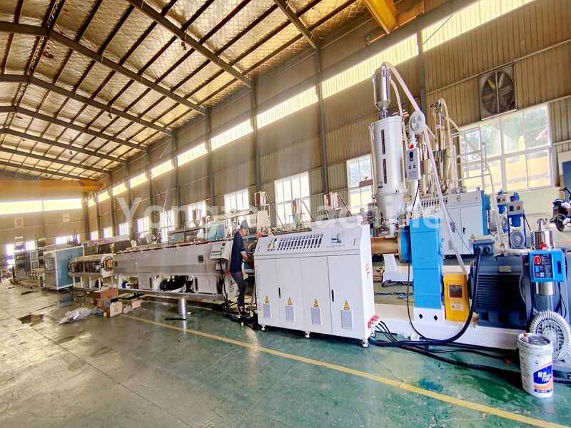
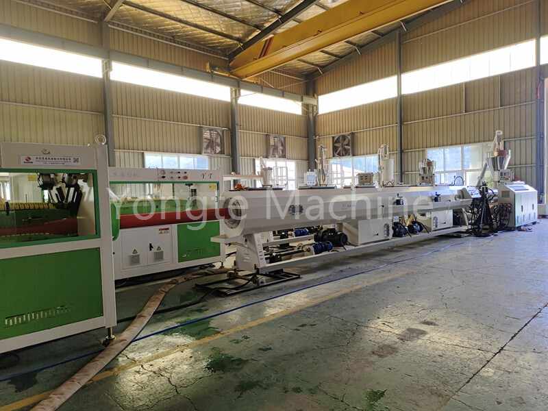
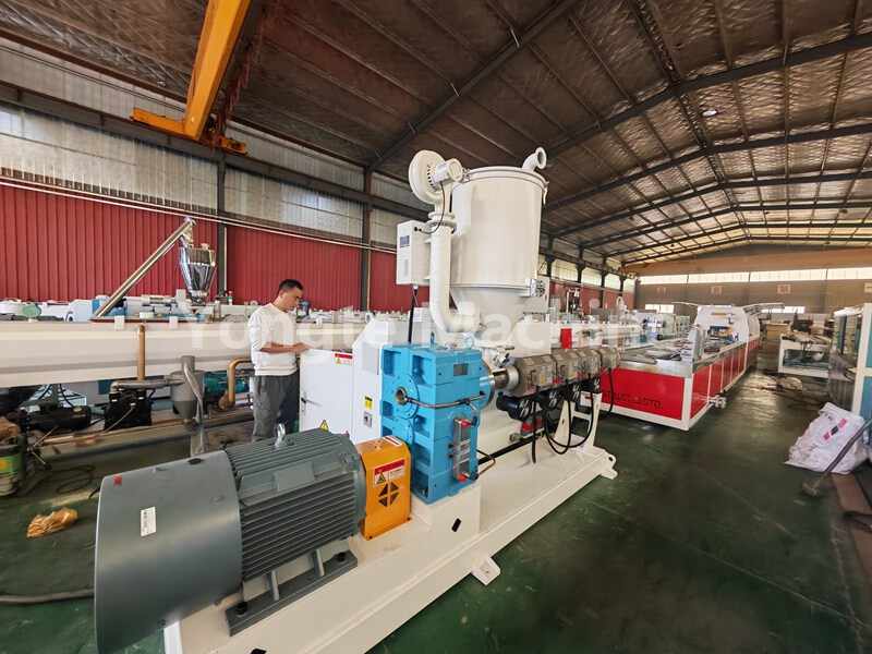
Yongte PVC rain gutter manufacturing machine is designed for the production of PVC rain gutter systems, which are used to collect and channel rainwater away from buildings. These machines are equipped to extrude, shape, cut, and package PVC materials into gutter components for residential, commercial, and industrial applications.
-
Wood Grain PVC Window Profile Co-Extrusion Line
 Wood Grain PVC Window Profile Co-Extrusion LineMore
wood grain PVC window profile co-extrusion line is a specialized manufacturing co-extrusion system designed to produce PVC window profiles that mimic the appearance of wood grain finishes. These profiles combine the durability and energy efficiency of PVC with the aesthetic appeal of wood, making them popular for both residential and commercial applications.
-
PVC Ceiling Making Machine
 PVC Ceiling Making MachineMore
Yongte PVC ceiling making machine is used in the production of PVC ceiling panels or tiles. These machines are designed to efficiently manufacture PVC ceiling products that are used for interior ceiling applications in residential, commercial, and industrial buildings.
-
Decorative Plastic Profile Equipment
 Decorative Plastic Profile EquipmentMore
Decorative plastic profile equipment refers to machinery and tools used in the production of plastic profiles that are used for decorative purposes in various applications such as furniture, interior design, construction, and more. such as skirt panel, ceiling panel, wall panel, furniture board, cardboard.
-
Conical Twin Screw PVC Profile Extruder
 Conical Twin Screw PVC Profile ExtruderMore
Yongte Conical twin screw PVC profile extruders is specifically designed for processing PVC (polyvinyl chloride) material using double conical-shaped intermeshing screws. The design and operation of these extruders are optimized for efficient processing of PVC materials with high throughput and product quality.
-
PP Plastic Profile Extruder
 PP Plastic Profile ExtruderMore
Yongte PP plastic profile extruder is a versatile machine used in the manufacturing industry to process polypropylene material into a wide range of profiles for various applications in construction, automotive, packaging, and other industries. Each step in the extrusion process plays a crucial role in producing high-quality PP profiles with consistent dimensions and properties.
-
UPVC window profile production line
 UPVC window profile production lineMore
Yongte UPVC window profile production line involves a series of processes that transform raw UPVC (unplasticized polyvinyl chloride) materials into finished UPVC window profiles ready for installation in windows and doors. Each step in the production line is crucial to ensuring the quality and accuracy of the final product.
-
Automatic PVC Profile Extrusion Machine
 Automatic PVC Profile Extrusion MachineMore
Yongte Automatic PVC profile extrusion machine transform PVC raw materials into profile products with specific shapes and sizes through a series of mechanical and thermal actions automatically.
-
High Speed PVC Profile Production Line
 High Speed PVC Profile Production LineMore
Yongte High Speed PVC Profile Production Line is generally composed of auto feeder, high effective extrusion system, high speed mold, fast calibration and cooling table, pull off device, auto cutting device, and control system.
-
PE/PP Plastic Lumber Extrusion Line
 PE/PP Plastic Lumber Extrusion LineMore
.
-
ABS Profile Extrusion Machine
-
Plastic Sheet Production Line
-
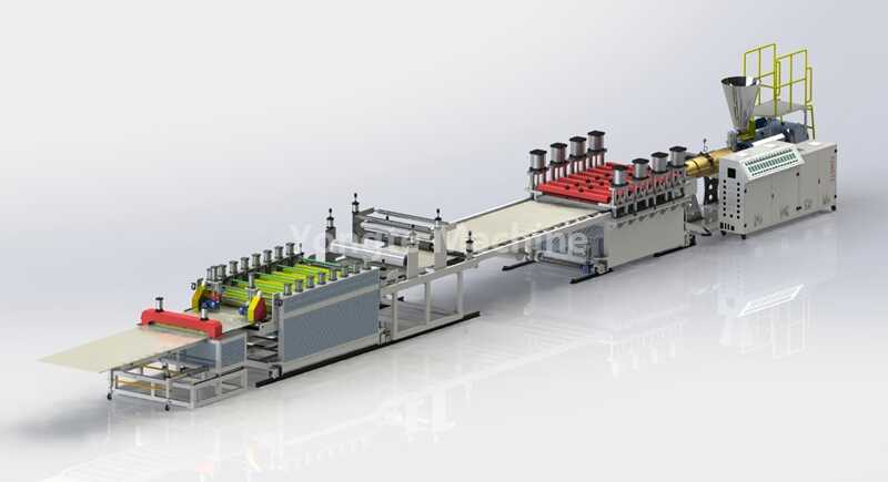
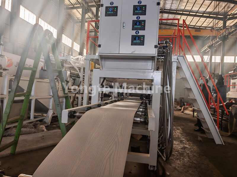
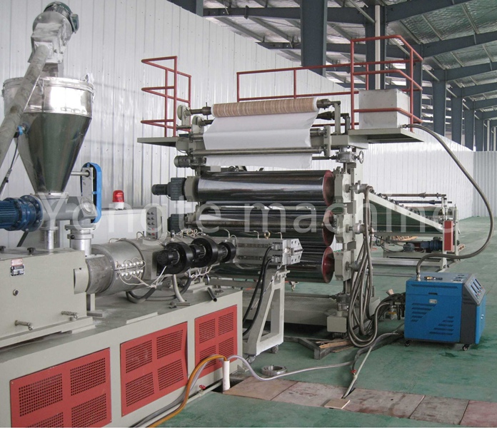
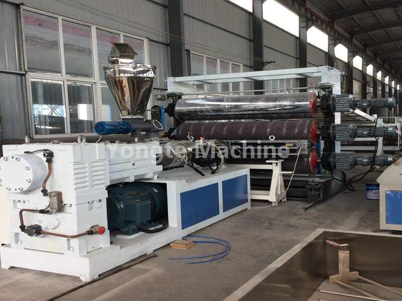
Multi-layer Co-extrusion Plastic Sheet Production Equipment
 Multi-layer Co-extrusion Plastic Sheet Production EquipmentMore
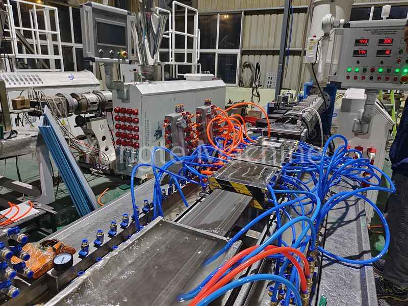
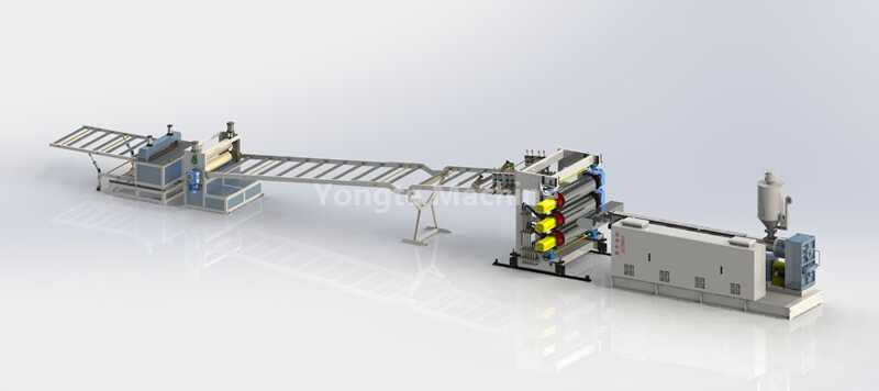
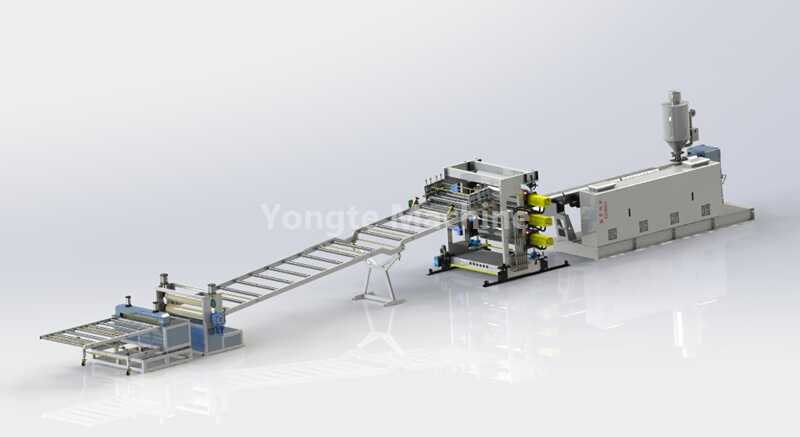
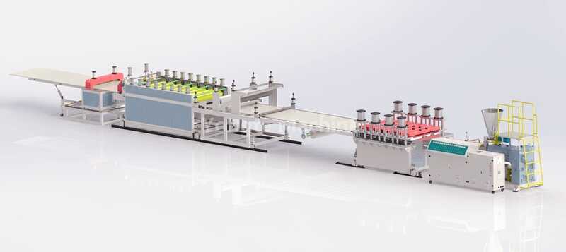
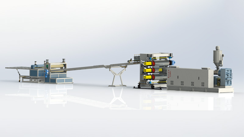
Yongte multi-layer co-extrusion plastic sheet production equipment enables the precise and efficient manufacturing of composite plastic sheets with specific layer configurations, properties, and functionalities tailored to diverse industrial, packaging, construction, and other applications. The equipment ensures the uniformity and consistency of the multi-layer sheets, meeting the required quality and performance standards.
-
Plastic Board Extrusion Machine
 Plastic Board Extrusion MachineMore
Yongte plastic board extrusion machine is a specialized piece of equipment used in the manufacturing industry to produce plastic boards of various types, sizes, and specifications. These extrusion machines are designed to process plastic resins into flat sheets or boards suitable for a wide range of applications, including signage, construction, packaging, and more.
-
WPC Semi-crust Foam Board Making Machine
 WPC Semi-crust Foam Board Making MachineMore
Yongte WPC (Wood-Plastic Composite) semi-crust foam board making machine is used to produce semi-crust foam boards made from a combination of wood fiber or flour and plastic resin. These boards are lightweight, durable, and have a semi-foamed structure that provides insulation and soundproofing properties.
-
PVC Foam Board Extrusion Line
 PVC Foam Board Extrusion LineMore
Yongte PVC foam board extrusion line is a specialized production system designed for manufacturing PVC foam boards, which are lightweight, durable, and versatile materials used in a wide range of applications, including signage, furniture, construction, and more.
-
LVT Floor Extrusion Machine
 LVT Floor Extrusion MachineMore
Yongte LVT Floor Extrusion Machine is core equipment for producing high-quality floor sheet, it is enabling fully automated production from raw material processing to finished product cutting. Key advantages include high-efficiency production, controllable quality, energy saving, and environmental friendliness, significantly reducing production costs and enhancing product competitiveness.
-
SPC Floor Sheet Production Line
 SPC Floor Sheet Production LineMore
SPC is short name of Stone Plastic Composite. Its advantages are wear-resistant, deformation-resistant, and environmentally friendly. Yongte SPC Floor Sheet Extrusion Machine are the core equipment for producing stone plastic flooring. it has advantages of high capacity, high automatic, high-filler plasticization, saving power, easy operation and maintainence.
-
PVC Free Foamed Sheet Extrusion Line
 PVC Free Foamed Sheet Extrusion LineMore
Yongte PVC Free Foamed Sheet Extrusion Line is used for making PVC foamed sheet from PVC and CaCo3, the PVC foamed sheet is widely used for advertisement, construction and decoration, our PVC free foamed sheet extrusion line has the advantages of high capacity, high automatic, easy operation, stably production, easy maintainence and saving power.
-
PVC Marble Sheet Making Machine
PVC Marble Sheet Making MachineMore
Yongte PVC Marble Sheet Making Machine is used for making marble surface sheet from PVC and CaCo3, the PVC marble sheet is widely used for wall panel decoration, furniture surface and partition wall. our machine has advantage of high speed, high quality, easy operation, easy maintainence, and low power consumption.
-
PE sheet making machine
 PE sheet making machineMore
Yongte PE sheet making machine is used for making PE sheets/plates/boards with different width and thickness. it mainly composed of materialfeeder, extruder,T die, three-roll calender, cooling bracket, haul off machine, cutting machine, coiler machine and electric control system.
-
ABS Plate Production Machine
 ABS Plate Production MachineMore
Yongte ABS Plate Production Machine is used for making ABS sheets/plates/boards with different width and thickness. it mainly composed of material feeder, extruder,T die, three-roll calender, cooling bracket, haul off machine, cutting machine, coiler machine and electric control system.
-
Multi-layer Co-extrusion Plastic Sheet Production Equipment
-
Plastic Recycling Machine
-
High-Efficiency Plastic Film Wastage Recycling Machine |
 High-Efficiency Plastic Film Wastage Recycling Machine |More
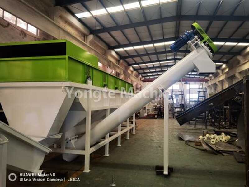
Our automatic plastic film wastage recycling machine solves tangling issues—handles PE/PP/mulch film (500 kg/h). Save 90% labor, CE/ISO certified. Get custom quote!
-
500kg/h Plastic Bottle Recycling Machine
 500kg/h Plastic Bottle Recycling MachineMore
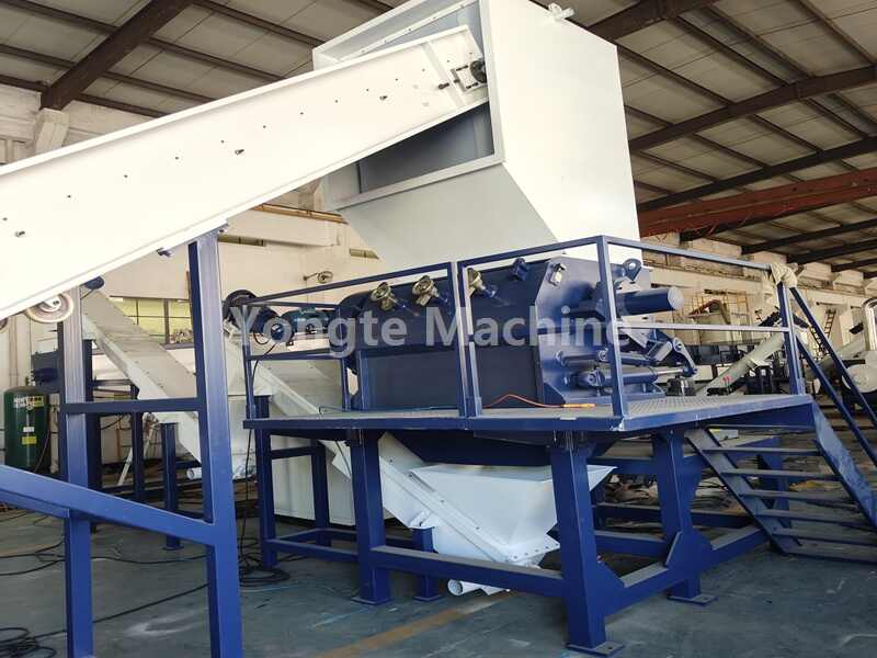
Our automatic plastic bottle recycling machine handles PET/HDPE bottles (500 kg/h). Save 80% labor cost, eco-friendly & durable—ideal for recycling stations/factories, CE certified. Get quote!
-
Plastic Crushing Machine
 Plastic Crushing MachineMore
.
-
Crusher machine
 Crusher machineMore
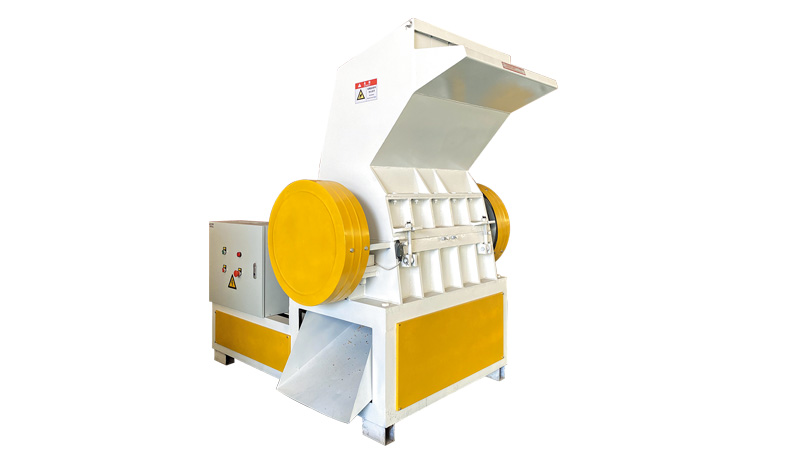
Main Technical Parameter:ModelSWP360SWP400SWP500SWP630Rotarydiameter360mm400mm500mm600mmRotatingblades3pcs5pcs12pcs12pcsFixedblades2pcs2pcs2pcs2pcsMotorpower15kw30kw37kw45kwCapacity200-300kg/h400-500kg/h400-1000kg/h700-1500kg/h
-
Plastic granulation machine
 Plastic granulation machineMore
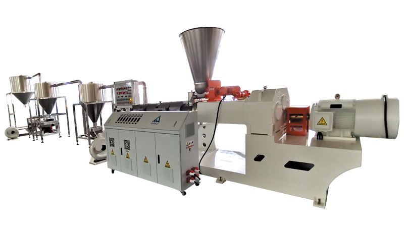
Plastic granulator is a device used to process waste plastic or plastic raw materialsinto plastic granules. it plays an important role in the plastic recyclingindustry andthe production of plastic products, providing key support for the recycling andprocessing of plastics.Its main components include
-
Mixer Machine
 Mixer MachineMore
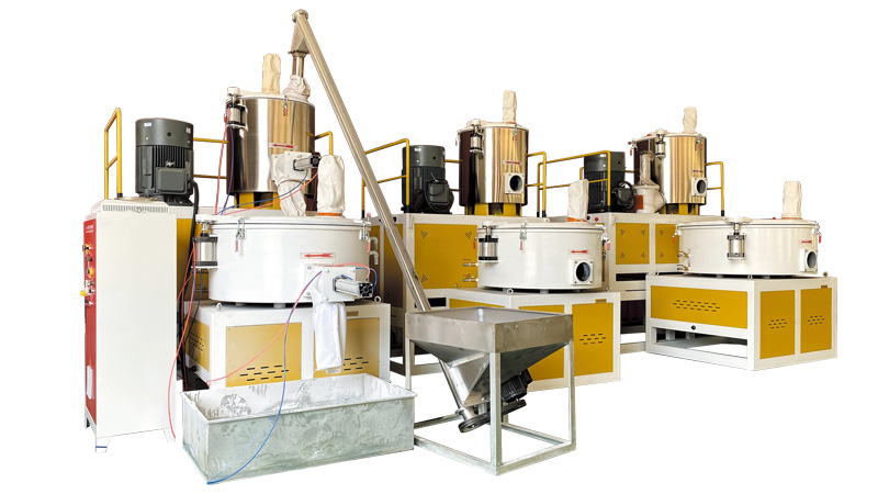
Main Technical Parameter:ModelSRL-200/500SRL-300/600SRL-200/500SRL-800/2000SRL-200/500Total Volume200L/500L300L/600L500L/1000L800L/2000L1000L/3000LValidVolume120L/300L180L/360L300L/600L480L/1200L750L/2000LHot mixer power30/42kw40/55kw75kw inverter control90kw Inverter control132 kw Inverter c
-
Rubber tyre recycling machine
 Rubber tyre recycling machineMore
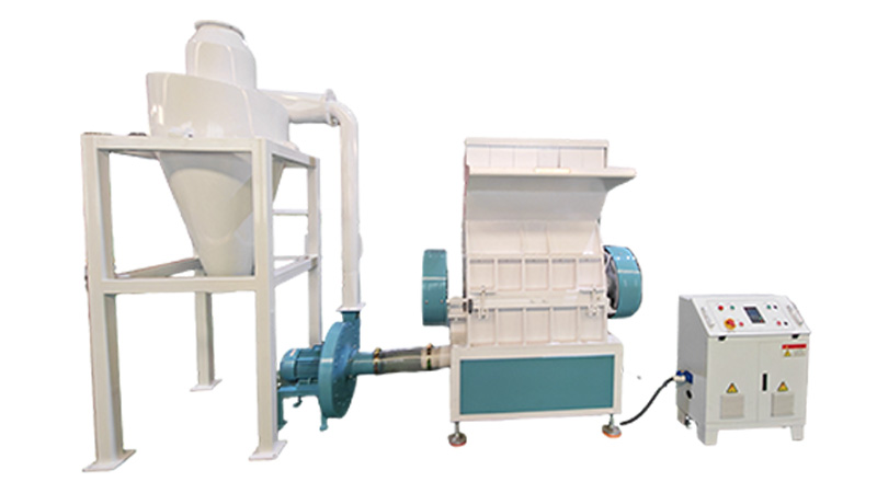
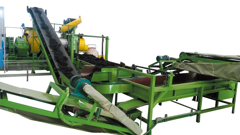
This machine is used for recycling the wasted rubber tyre into rubber powder,it includes the functions ofwire ring rulling, primary cutting, tyre shredding, rubberblocks crushing, and rubber powder grinding.
-
High-Efficiency Plastic Film Wastage Recycling Machine |
-
Auxiliary Equipment
-
Hot and Cold PVC Mixing Machine
Hot and Cold PVC Mixing MachineMore
YT Machinery’s Hot and Cold PVC Mixing Machine is a top-tier plastic auxiliary equipment for industrial plastic processing. High-efficiency, durable, and reliable – ideal for your mixing needs. Choose YT for quality machinery!
-
Film slitter machine
 Film slitter machineMore
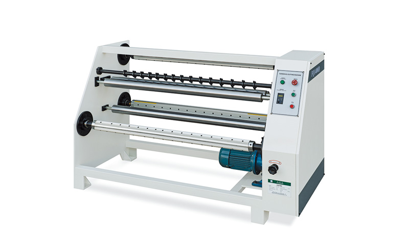
.
-
Vacuum lamination machine.
 Vacuum lamination machine.More
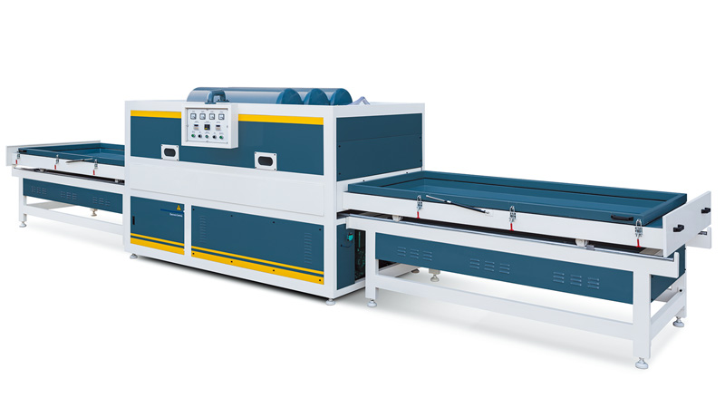
This machine is used for surface lamination of pVc board, MDF board, WPCfoam board, and WPC door board with modeling surface after CNC engraving.The lamination material generally is PVC film. This machine uses cold glue.
-
PUR350 lamination machine
 PUR350 lamination machineMore
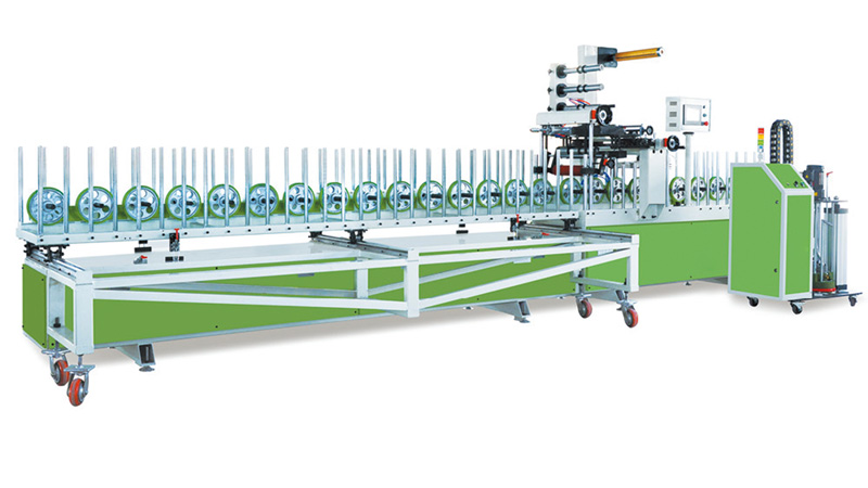
This machine is used for surface lamination of PVC windows and doors profile.aluminum alloy windows and door profiles, MDF/WPC profile, etc. The laminationmaterial can be PvC film, paper, wood veneer, CPL, and leather. This machine usesPUR hot melt adhesive.
-
PUR1300 lamination machine
 PUR1300 lamination machineMore
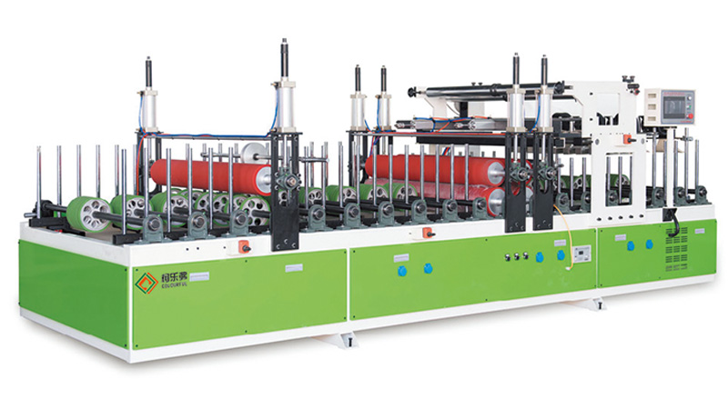
This machine is used for surface lamination of window sill, PVC board, MDFboard, WPC foam board, WPC door board, Aluminum sheet and other decorationproducts with smooth surface. The lamination material can be PVC film, paper,wood veneer, CPL, and leather. This machine uses PUR hot melt adhesive.
-
Double side sanding machine
 Double side sanding machineMore
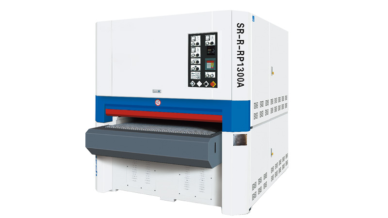
Double-side sanding machine is usedfor surface sanding of MDF/WPC/Woodboards and other materials. it can dosanding both front and back sides ofthe board at one time to remove surfacedefects, unevenness, burrs, etc., sothat the material surface can meetcertain flatness, smoothness androughness
-
Precision cutter
 Precision cutterMore
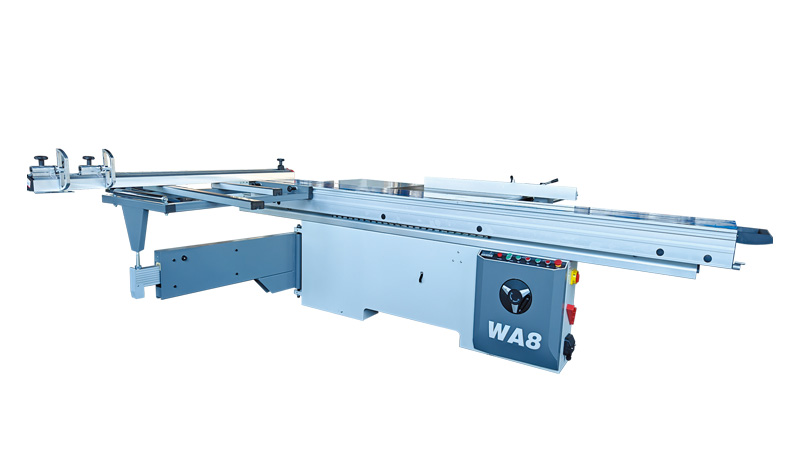
This machine is used for cutting the WPC products, it can work for lengthcutting, width cutting and angle cutting.
-
5 sides CNC Processing Machine
 5 sides CNC Processing MachineMore
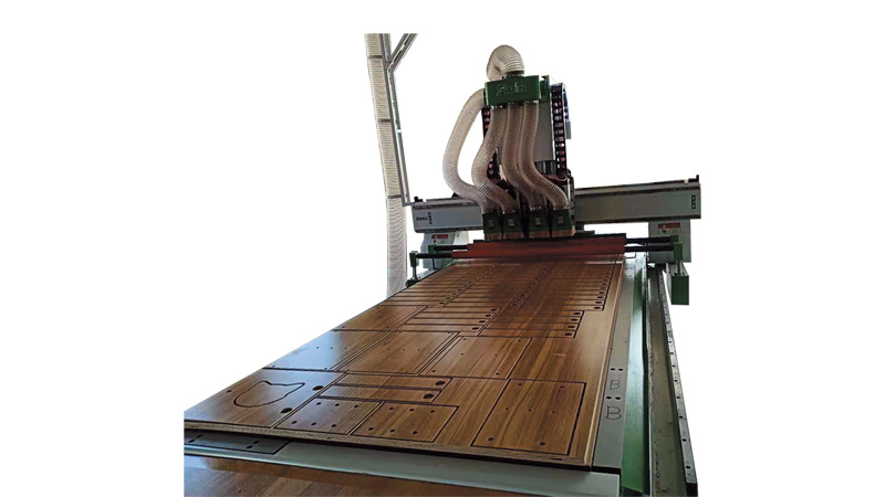
This machine has the processing functions of door panel CNC engraving andholes drilling for lock, hinge, lock core hole, dust-proof strip, fireproof strip, doorcloser, cat's eye,and glass frame.
-
Offline 2D Embossing Machine
 Offline 2D Embossing MachineMore
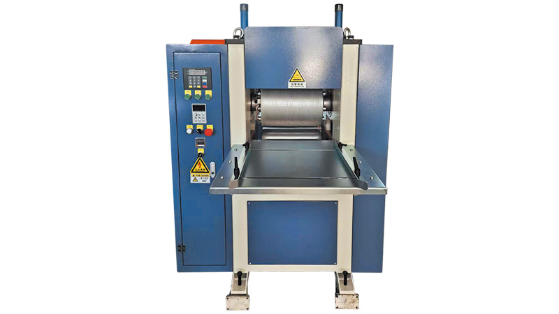
This machine is used for 2D embossingdesign, it will be used after the extrusionline when the WPC products are cooled.
-
online 3D Embossing Machine
 online 3D Embossing MachineMore
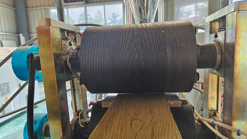
Embossing machine: it is used for making wooden pattern on the WPC productsby embossing rollers, it can be installed on the extrusion line to achieve 3D deepembossing, or used after the extrusion line to make light embossing in fast speed.Main Technical Parameter:Model0n-165On-295Off-295YT-1300Rolle
-
Sanding and brushing machine
 Sanding and brushing machineMore
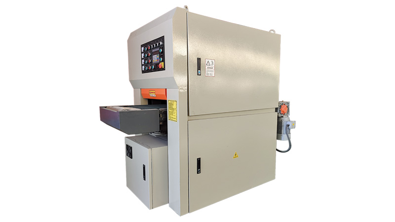
Sanding and brushing machine:sanding and brushing processing on WPCproducts can achieve rough wooden surfacebecause it take away the plastic surface,it also can be used after online embossingto achieve more real wooden feelingMain Technical Parameter:ModelSM-400SM-600SM-1000SM-1300Sanding width360m
-
Wood Powder Grinding Machine
 Wood Powder Grinding MachineMore
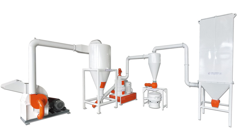
Yongte Wood Powder Grinding Machine can process various wood sawdust into wood powder: high capacity, low power consumption, easy maintenance, easy operation, low noise, long using life
-
Hot and Cold PVC Mixing Machine
-
Wood Plastic Composite WPC Machine
-
News
-
FAQ
-
Why yongte equip concial twin screw extruder for making WPC profiles?
 Why yongte equip concial twin screw extruder for making WPC profiles?More
Yongte's WPC conical twin screw extruders use bimetallic screws and SKD wear-resistant barrels, equipped with direct-drive vertical gearboxes, resulting in higher production stability.
-
What is the max. Moisture content of wood for making WPC products?
 What is the max. Moisture content of wood for making WPC products?More
Yongte reduces the impact of wood powder moisture by optimizing equipment design and production processes.
-
What raw materials can the WPC granulation machine process?
 What raw materials can the WPC granulation machine process?More
Yongte WPC granulation machine works with PP/PE recycled plastic (bottles, film, bags) and wood-based materials (sawdust, rice husks, wheat straw) with a wood powder content of 30-70%.
-
What type of plastic material should be used for making WPC products?
 What type of plastic material should be used for making WPC products?More
Yongte provides a diverse range of Wood Plastic Machines capable of manufacturing an extensive array of wood-plastic products using various raw material combinations, such as PE and wood composition, PVC and wood composition, and PP and wood composition.
-
WPC production process steps
 WPC production process stepsMore
Custom WPC production equipment from Yongte – tailor-made for PE/PVC/PP materials. High output, eco-friendly (recycled plastic compatible) & competitive price. Contact us for your project!
-
What fiber materials can be used for making WPC products?
 What fiber materials can be used for making WPC products?More
Yongte Wood Plastic machine can use different types of fiber wastage material to make WPC products
-
Can your WPC machine use fiberglass waste instead of wood flour?
 Can your WPC machine use fiberglass waste instead of wood flour?More
Yongte WPC machine can use waste PP/PE plastics and fiberglass waste to produce WPC products. This technology has been tested and verified by Yongte, and Yongte has already provided a complete set of production equipment for the recycling and reuse of fiberglass to produce WPC products to a Canadian customer.
-
Can your plastic pipe production line be automated?
 Can your plastic pipe production line be automated?More
Yongte PE PPR PVC Plastic Pipe Production Lines fully support automated production and have formed a complete automated process: raw material processing → extrusion molding → calibration and cooling → traction cutting → finished product inspection → product stacking.
-
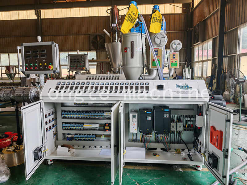
Should I choose PLC control system or Push-button control system when puchasing Yongte Plastic Extrusion Machine?
 Should I choose PLC control system or Push-button control system when puchasing Yongte Plastic Extrusion Machine?More
PLC control system is good for automatic plastic production machine. No matter you choose Push-button control system or PLC control system, Yongte team shall provide you high quality machine with good service.
-
Do you supply the documents for custom clearance for your plastic machine after delivery?
 Do you supply the documents for custom clearance for your plastic machine after delivery?More
Yes. we will provide the custom clearance documents to customer after delivery.After delivery the machines, Yongte Plastic Machinery provides the related complete set ofcustom clearance documentsto ensure smooth international transportation and customs clearance for your plastic processi
-
Can you give me a significant discount on the quoted plastic machine price?
 Can you give me a significant discount on the quoted plastic machine price?More
Dear valued customer, Yongte price is quoted based on our high quality plasticmachine and great service.There is an old Chinese saying: "You get what you pay for."And quality and price are directly proportional.I'm sure you can always find suppliers with lower quotes than mine
-
How to do maintainence for WPC Extrusion Machine
 How to do maintainence for WPC Extrusion MachineMore
Maintaining of WPC (Wood Plastic Composite) Extrusion Machine is critical to ensuring consistent product quality, extending equipment lifespan, and minimizing unplanned downtime. WPC extrusion involves abrasive wood fibers and heat-sensitive plastics, so maintenance must address unique challenges like material buildup, component wear, and thermal stability.
-
Why yongte equip concial twin screw extruder for making WPC profiles?
-
FAQ
- Contacts

